
Wastewater Equipment is the practical backbone of modern water protection. It removes solids, organic matter, nutrients, oils, and harmful microorganisms from used water. Without reliable treatment, even a clear-looking discharge may damage rivers, soil, and public health. The process often begins with screens that catch rags and plastics. Grit chambers then settle sand and small stones. Pumps move the flow between treatment stages, while tanks provide controlled spaces for separation and biological activity.
George Tchobanoglous, a leading wastewater engineering authority, wrote, “The objective of wastewater treatment is to produce an effluent that can be discharged to the environment without causing adverse effects.” That principle explains why equipment selection requires more than comparing prices. Operators must examine flow rates, contaminant levels, temperature changes, maintenance access, energy use, and local discharge requirements. A biological reactor may need precise oxygen control. A filter may require frequent backwashing. Sludge equipment must handle thick, unpredictable material.
Small details matter. A blocked screen can raise upstream levels within minutes. A failing blower can reduce dissolved oxygen and weaken biological treatment. No system is perfect. Designs can still overlook seasonal flows, operator training, or difficult cleaning conditions. Good practice includes monitoring, preventive maintenance, clear records, and realistic performance testing. This article explores how Wastewater Equipment works, where each unit fits, and why dependable treatment depends on coordinated equipment rather than one impressive machine.
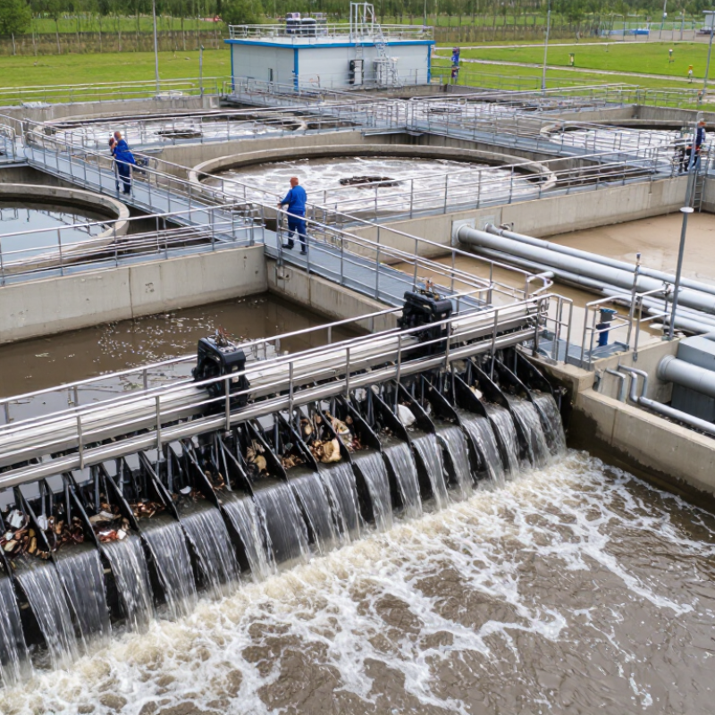
Wastewater equipment is best understood as a process map, not a single machine. At the inlet, coarse screens remove rags, plastics, and larger debris. Grit chambers then settle sand before it damages pumps. Equalization tanks soften sudden flow and pollution changes. That step is often underestimated. Real plants rarely receive a perfectly steady stream.
Primary clarifiers remove settleable solids. Biological reactors use microorganisms to reduce dissolved organic matter and nutrients. In practical operation, oxygen control matters because excessive aeration wastes energy. Secondary clarifiers separate treated water from biological solids.
The International Water Association reports that energy can represent 25–40% of a treatment plant’s operating costs.
Tertiary filters, membranes, or nutrient-removal units polish the stream. Disinfection follows, using methods such as ultraviolet light or carefully controlled chemical treatment.
The UN World Water Development Report 2024 notes that roughly 80% of global wastewater is discharged without treatment. That figure makes reliable process control more than an engineering preference.
Tips: Map every flow, including sludge, return liquor, and bypass routes. Check sensors against laboratory results, not software alone. Reuse may require filtration, disinfection, and monitoring for specific contaminants. Local health and environmental rules decide the final quality target. A common weakness is designing for average flow only. Peak storms expose it. Sludge handling also deserves attention; dewatering equipment can change hauling volume, odor, and operating cost. I would question any design that promises reuse without identifying its end user, monitoring plan, and failure response.
Wastewater equipment begins working before biological treatment starts. Preliminary treatment removes large debris and heavy mineral particles from incoming sewage. This stage protects pumps, valves, pipes, and later treatment units from avoidable damage.
Screens catch rags, wipes, plastics, wood, and other coarse material. Coarse screens usually stop larger objects, while finer screens capture smaller fibers and solids. As debris builds, water levels rise upstream. Operators should check the differential level, rake movement, and discharge area during each inspection. A screen can appear functional while hidden material reduces its capacity. Small oversights become expensive blockages.
Grit removal targets sand, gravel, eggshell fragments, and other dense particles. These materials can settle in channels or enter pumps, causing abrasion and unstable flow. Vortex, aerated, and horizontal-flow grit chambers control water velocity so grit settles without removing too much organic matter. The balance is not perfect. Excessive velocity carries grit forward, while low velocity may trap useful solids. Field staff often examine the grit hopper, wash system, and pump noise together. Unusual vibration deserves attention. It may indicate worn impellers, poor screening, or grit accumulation. Regular removal also matters, because stored grit reduces chamber volume and can harden into difficult deposits.
| Equipment or Process | Primary Purpose | Typical Opening or Separation Range | Typical Design Considerations | Material Removed | How It Protects Pumps | Common Maintenance Requirement |
|---|---|---|---|---|---|---|
| Coarse Bar Screen | Captures large floating and suspended debris before it reaches downstream equipment. | Approximately 25–75 mm bar spacing | Usually installed at the influent channel; may be manually or mechanically cleaned. | Rags, sticks, plastics, cans, wood, and other large solids | Reduces the risk of clogging, shaft damage, and impeller blockage. | Frequent inspection and removal of accumulated screenings; cleaning frequency depends on the solids load. |
| Fine Screen | Removes smaller solids that pass through coarse screening. | Approximately 1.5–6 mm openings | Requires reliable screenings handling and washing or compaction where applicable. | Small plastics, fibers, paper fragments, food particles, and fine debris | Limits blockage of pump passages, valves, pipes, and treatment units. | Monitor differential water level, inspect screen surfaces, and maintain the cleaning mechanism. |
| Step Screen | Uses a moving stepped-screen surface to lift and remove screenings continuously. | Commonly about 3–6 mm openings | Suitable for channels where continuous mechanical screening and a relatively compact layout are desired. | Fine-to-medium screenings, including fibrous solids and plastics | Provides consistent solids removal and helps prevent intermittent pump clogging. | Inspect moving steps, drive components, spray systems, and screenings discharge areas. |
| Rotary Drum Screen | Separates solids as wastewater passes through a rotating perforated or wedge-wire drum. | Often about 0.5–6 mm, depending on the design | Needs adequate spray-water control and a suitable screenings discharge arrangement. | Fine suspended solids, fibers, hair, and organic particles | Reduces fine-solid accumulation in pump suction lines and downstream process equipment. | Clean the screening surface, inspect spray nozzles, and check drum bearings and drive components. |
| Grit Chamber | Removes dense inorganic particles while allowing most lighter organic solids to remain in suspension. | Designed to remove particles commonly around 0.15–0.20 mm and larger | Flow control is important; excessive velocity carries grit forward, while low velocity may settle organic solids. | Sand, gravel, glass fragments, eggshells, coffee grounds, and other dense mineral particles | Prevents abrasive wear, impeller erosion, pipe deposition, and reduced pumping capacity. | Remove accumulated grit routinely and inspect scrapers, air systems, pumps, or classifiers where installed. |
| Aerated Grit Chamber | Uses air to create a rolling flow that separates heavy grit from lighter organic matter. | Typically targets grit around 0.15–0.20 mm and larger | Airflow and detention conditions must be controlled to maintain effective grit separation. | Dense inorganic grit with reduced quantities of settleable organic material | Reduces abrasive particles entering lift pumps and protects mechanical components. | Check air headers, diffusers, blowers, grit collection equipment, and settled-material removal. |
| Vortex Grit Removal | Creates a controlled circular flow that concentrates grit for collection. | Commonly designed for grit around 0.15–0.20 mm and larger | Maintains separation through hydraulic geometry and controlled flow rather than prolonged settling. | Sand, gravel, glass, and other high-density inorganic solids | Limits abrasive wear and reduces the chance of grit settling in pump wet wells and force mains. | Inspect the vortex mechanism, grit pump, collection hopper, and discharge piping. |
| Grit Washer and Classifier | Washes and dewaters collected grit to reduce organic content and disposal volume. | Processes grit captured by the selected grit-removal unit | Improves handling characteristics and may reduce odors and putrescible material in the grit stream. | Collected mineral grit with attached organic solids | Does not directly screen wastewater, but supports reliable grit removal before pumping and later treatment. | Inspect augers, wash-water sprays, bearings, discharge chutes, and dewatering performance. |
| Influent Pump Wet-Well Protection | Combines screening, grit removal, level control, and pump inlet design to protect lift-station pumps. | Site-specific; based on pump passage size, flow, and solids characteristics | Requires proper screen capacity, adequate submergence, anti-vortex provisions, and accessible cleaning points. | Residual screenings, grit, and settleable solids not removed upstream | Reduces clogging, cavitation risk, abrasion, odor-related deposits, and unplanned pump shutdowns. | Inspect wet-well levels, pump starts, vibration, current draw, alarms, and accumulated solids. |
In wastewater treatment, primary clarification is the quiet mechanical step before biological treatment. Wastewater enters a large settling tank, where flow slows enough for heavier solids to sink. Grease and floating debris rise to the surface. Scrapers collect settled sludge, while skimmers remove the floating layer. Clarified liquid leaves through overflow weirs and moves toward the biological stage. The equipment seems simple. Its control is not.
Effective settling depends on detention time, tank geometry, temperature, and flow changes. Operators watch sludge depth, surface patterns, and outlet clarity. A sudden storm can push solids through the tank before they settle. Excessive sludge storage can also cause odors and rising solids. In practice, a design may look correct on paper yet perform poorly after uneven loading. Small adjustments to pumping rates or sludge withdrawal can protect downstream biology. Measurements matter, but experienced observation still catches problems early.
Tips: Keep inlet channels free of grit and check scraper movement routinely. Record sludge blanket depth, scum accumulation, and effluent appearance. Do not judge performance from one sample. Compare results across several operating periods. Leave room for doubt. A cloudy outlet may reflect hydraulic stress, not only equipment failure. When readings conflict, verify the instrument and inspect the tank before changing settings.
Biological treatment is the living engine inside many wastewater systems. In an aeration basin, microorganisms consume dissolved organic matter measured as biochemical oxygen demand, or BOD. Air diffusers add oxygen, while mixers keep solids suspended. The water then enters a secondary clarifier, where biological solids settle. Some return to the basin. The rest leaves as waste activated sludge.
Under the United States Environmental Protection Agency’s secondary treatment framework, treatment facilities commonly target at least 85% BOD5 removal. This performance goal compares the influent and effluent BOD5 loads, not just their visible clarity. Facilities also monitor permitted concentration limits, often near 30 milligrams per liter as a monthly average. Actual requirements can vary by permit and location. Operators collect representative samples and review oxygen levels, sludge settling, temperature, and flow changes.
Small details matter. Brown, stable foam may indicate normal biological activity, while rising sludge can signal poor settling or low oxygen. Heavy rain can dilute wastewater and upset the process. Cold water slows microbial growth. It is easy to trust one laboratory result too much. A single sample cannot explain a week of unstable operation. Reliable control comes from repeated testing, calibrated instruments, and experienced operators who compare trends. The 85% target is useful, but it is not a promise that every basin performs perfectly every day.
Disinfection is the control point between treated wastewater and safe reuse. It targets bacteria, viruses, and other pathogens that may remain after biological treatment. The equipment must match the water quality, flow rate, and intended use. Clear water helps ultraviolet systems work effectively. Suspended solids can shield microorganisms from light.
Chlorine systems add a measured disinfectant and maintain contact time in a dedicated tank. Operators check residual levels, pH, turbidity, and flow records throughout the day. Ultraviolet equipment uses lamps and controlled exposure time instead. It leaves no chemical residual, but dirty sleeves reduce performance. Ozone can also reduce pathogens and odors, although it requires careful process control and energy management. Small details matter.
Reuse needs stricter discipline than appearance suggests. Water may look clean and still carry invisible hazards. Irrigation, toilet flushing, and industrial uses each require different treatment targets and monitoring plans. Automatic alarms should flag low disinfectant levels or reduced UV intensity. Backup systems are valuable during power or equipment failures. They are not magic, though. Maintenance delays can weaken protection quickly. A practical operator keeps sampling points accessible, documents unusual readings, and questions results that seem unusually perfect. Disinfection is not a single machine; it is a controlled barrier supported by testing, trained judgment, and responsible reuse planning.
Wastewater Equipment is a connected system that moves wastewater through several treatment stages, transforming polluted water into a safer effluent suitable for discharge or reuse. The process begins with preliminary treatment, where screens capture large debris and grit removal protects pumps and downstream machinery. In primary clarification, settling tanks separate suspended solids before the water enters biological treatment. Microorganisms then break down organic pollutants, with treatment targets often focused on removing about 85% of biochemical oxygen demand (BOD).
After biological treatment, disinfection reduces harmful pathogens and helps control risks in treated effluent intended for release or reuse. At the same time, separated solids undergo sludge processing to reduce volume, stabilize organic matter, and recover useful energy. Anaerobic digestion can produce biogas containing approximately 60–70% methane, making sludge management an important part of resource recovery. Together, these stages create an efficient process map from inlet protection to treated water and by-product management.

2025 Bio-Botanica, a division of Bio Answer Holdings Inc. All Rights Reserved.